
Process modeling is performed in the system process design tool. After starting, the main tool window appears. This window consists of the following parts (see Figure 1 ):
- The menu panel provides all commands related to managing processes and their elements, as well as the configuration and operation of the process design tool itself. This panel also includes a toolbar that allows quick access to the most important commands related to managing processes,
- Process definition list panel displaying all defined and shared Processes . For each Process , after expanding its node, you can access its components, i.e. activities , Transitions and Data Container ,
- Process panel enabling modeling and defining a process selected from the process list. The Model tab is used for modeling. The Definition tab is used for detailing the model (defining it) .
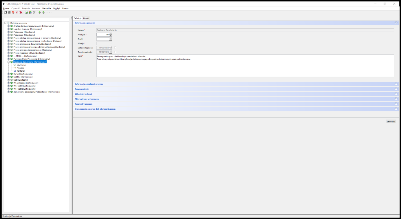
Figure 1. The main window of the Process Definition Editor
Basic navigation elements
For all elements available in the process design tool user interface, there are several common, standard (known from Windows) rules for their operation:
- BPMN symbol selection is done by clicking the left mouse button once on this symbol. The selected symbol is outlined with a line (sometimes dashed) in green. Additionally, the selected symbol has so-called selection points on the frame, which allow changing its dimensions after clicking the left mouse button and dragging the mouse in the desired direction.
- changing the symbol name only applies to the selected symbol. To change the name, double-click the left mouse button or press the F2 key .
- The symbol name is automatically split into lines . To force a different splitting of the name, press the Shift Enter key combination at the line break . To finish entering the name, press the Enter key .
- After pressing the right mouse button for the selected symbol, a context menu is available. Within this menu, it is possible to set the symbol's color scheme. Depending on the symbol type, the following may also be available:
- definition of a given symbol – via the " Properties " items
- copying a given symbol – via the “ Copy ” item. Pasting a copied symbol is done by selecting the “ Paste ” item from the context menu. This item is available when the Role in the process is selected. In the case of copying, the user is obliged to ensure the uniqueness of the identifiers of the copied elements.
- Task participant role – in the lower left corner of the " Model " panel , a legend of the roles adopted for a given process model is displayed.
- To select a group of symbols , hold down the " Shift " key and click on the appropriate symbols one by one. Then, simply press the right mouse button on one of the selected symbols and, while holding it, drag the symbol (group of symbols) to the appropriate place.
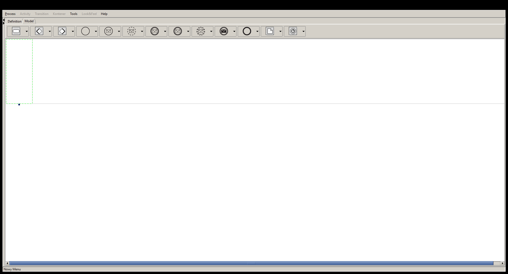
Figure 2. The Process Definition Editor Graphic Symbols Menu
Having defined activities, we supplement the information about the control flow determining the order and conditions of performing activities in the process. At the stage of process modeling, this concerns two elements: Transitions between activities and control separation and connection operators .
To draw a transition:
- hover over the action from which we will define the transition – we assume that it is action A. The mouse should change its appearance to a hand with a straight index finger,
- click the left mouse button and, holding the button pressed, drag the mouse to the activity to which the transition is to be defined. We assume that this is activity B.
- An arrow appears on the screen from activity A to activity B.
To "break" the transition you must:
- mark the transition,
- click on the crossing with the right mouse button – at this moment a new break point will appear on the crossing,
- left-click on the created bend point and drag it to the appropriate place.
The transition break can be repeated multiple times. To undo the break, reselect the break and right-click on the break you want to remove.
Process modeling
Creation of the process
To start modeling and defining a process, you need to create it in the designer tool. In docuRob® WorkFlow, there are two ways to do this: create a completely new process or create it based on an existing process.
In the first case you should:
- select the Process->Create menu item ,
- enter basic data regarding the new definition, including:
- Name – this is a unique name for the process. Since the process name can be used by external systems integrated with the docuRob®WorkFlow system , it is recommended to check what format the process name supports. For example, some systems recommend avoiding the use of special characters.
- Priority – defines the relative importance of processes in terms of the order in which process tasks are handled by the docuRob®WorkFlow platform .
- Version - specifies the process version that is currently being defined or modified. In the event of a modification to an already shared process, the modified version automatically receives a consecutive number. In this way, docuRob®WorkFlow uniquely identifies all versions of a given process. When a process is created, the product automatically assigns version number 1 to the process definition.
- Description – text description of the process being created.
After creating the definition, the process name appears in the Process Definition List panel . After clicking on the process , in the right panel you can go to the Model tab and start the actual process modeling.
The model is saved automatically when adding symbols. Manually forcing the model to be saved occurs after switching from the Model tab to the Definition tab.
Roles in the process
Proper process modeling starts with identifying and drawing the roles in the process. In our example (Process: POA_Order ) we identify four roles:
- Sale
- API_ERP
- Management
- Client
It is worth noting that the role names are not related to the organizational structure. In particular, it would seem natural to name the role Acceptor – Manager , and the Acceptor finally – Director . Unfortunately, this would not be the best solution for two reasons:
- for some employees, especially managers and executives, this would be confusing,
- In the event of changes in the organisation, for example assuming that the final approval is performed by the head of the employment department, it would be necessary to change the role name in the process and, at least in some cases, re-train the employees.
According to the BPMN v. 2.02 standard guidelines, a Role in a process is represented by a so-called Swimlane . To add a new Role , click on the process role symbol located on the toolbar.
The definition of the roles of process participants and the selection of the color of the appropriate task symbols is created in the context menu of the process in the " Roles " tab. The role name must be entered and the color selected.
In the case of complex process graphs, especially those that use event-driven Subprocesses , the Swimlane technique of marking participant roles makes it difficult to build readable models. As an alternative approach, we propose marking the Roles of process participants with the fill colors of the appropriate Task symbols according to the descriptions of the individual roles presented at the bottom of the graph. Actions concerning the graphical appearance of the role symbol (i.e. changing the color scheme, expanding, removing the role, etc.) are performed according to the standard rules described above in this section.
Exporting a graphical representation of the model
If we want to obtain a graphical representation of the process model (graph), then being on the Model tab of the process, select the menu item Process -> Save Graphics . The model is saved in one of the selected four graphic formats: GIF, PNG, JPG and SVG.
Export and import model
At any point in the modeling process, it is possible to export the process model. The model is saved in the standard XML Process Definition Language v. 2.0 format. This model can then be loaded on the same server or any other. This allows for the dissemination of knowledge about the process(es) by sharing their models saved in the standard XPDL language.
To export a process, you must:
- select the menu item Process -> Export
- specify the name of the file where the process model will be saved
- click the Export button .
The file is saved with the extension xml . This file can be viewed in any XML editor.
A saved model can be imported. The import can be done into an existing process. To do the import:
- in the process definition list panel, select the process to be imported. This process must be in the Defined state.
- select the menu item Process -> Import . Select the file to import
- click the Import button .
In case of import errors, information will be displayed on the screen indicating the possible cause of the errors.
Additionally, it is possible to import an existing process or create a process based on an imported process using the " drag and drop " mechanism. To do this, you must:
- open the window with the imported file
- open the process design tool with the process definition list panel visible
- drag and drop the file onto: a) the process definition – this will import a new definition, b) the top of the definition tree – this will start creating a new process with import of the selected file.
Creating a process based on an existing one
You can also create a Process (its model) based on an existing process. To do this, select the Process -> Create from Existing menu item and provide data about the process being created, along with selecting an existing process from the drop-down list, based on which the new process will be created.
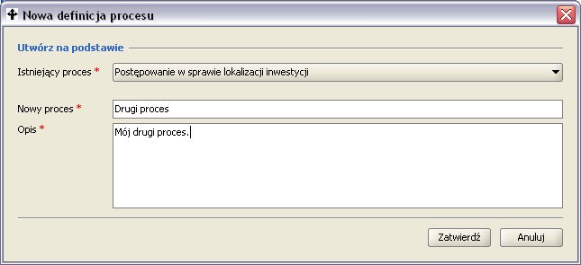
Rysunek 7: Tworzenie procesu na podstawie już istniejącego
Rysunek 7: Tworzenie procesu na podstawie już istniejącego
Process Definition Management
Typically, the first, complete process implementation is the initial, not final, stage of the launch of the final version of the process. Subsequent stages include pilot implementation and full production implementation of the process, which ultimately indicate areas in the process requiring improvement. These and other change needs are handled in the docuRob®WorkFlow system in a standard manner, in accordance with the process definition life cycle.
The life cycle of a process definition is presented in Figure 4 . The basic assumption is that the process definition is versioned. Each version of the process definition has its own separate life cycle and is saved in the process definition repository available in the system.
When a process definition is created, its first version is automatically created. This process version is in the defined state . In this state, the process can be modeled and its definition can be refined. At any time, the process definition (or the model itself) being developed can be imported or exported. The correctness of the work performed can be checked by running process verification. When the process definition is complete and correct, it can be made available. As a result of this operation, the process version status changes to available . In this state, the process can be run according to the new definition. In this state, the complete process definition can also be exported.
If it is necessary to modify the version, the modify service should be executed . This service will create a new (next) version of the process definition, which will remain in the defined state and, similarly to the previous version, it will be possible to work on it. At the same time, the possibility of starting processes according to the last shared definition is retained. If the changes made are not as expected, the new version can be deleted. This is equivalent to deleting the newly created, working version and returning to the previous version of the process in the available state . After the new (second) version has been made available, it is still possible to delete it. This is possible if no instance of this process version has been started. Otherwise, deletion is not possible. If there is no process instance associated with the first version of the process definition, the entire definition can also be deleted.
Process definition versions are numbered with consecutive integers starting from 1. The number of versions is not limited. When exporting a version, information about the exported version is saved in the file name and additional definition attributes.
All historical versions of a process definition are stored in the definition repository in the docuRob® WorkFlow system. These definitions are used to analyze executed processes that were run according to a given definition.
The following subsections describe the individual services available within the process definition management lifecycle.
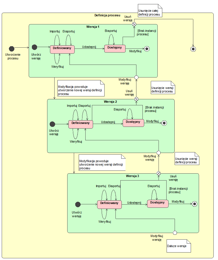
Figure 4. Process/Sub-process definition life cycle
Verification
Verification of the process definition consists of a comprehensive correctness check of the process. Unlike the verification of individual elements performed during data entry, this verification includes all elements of the model and process definition, in particular checking:
- consistency of the process model, correctness of inputs and outputs, control flow in the flow elements and control connections, identification of hanging activities (i.e. not connected to the rest of the graph),
- completeness of data regarding global process variables stored in the process container
- BPQL rule correctness, including:
- Participant assignments
- transition conditions
- pre and post action
- assigning parameters of called applications and exception handling definitions
- incorrect dependencies between activities in the basic scope (e.g. missing condition at decision transition, etc.)
- correctness of the defined quality constraints on the process, in particular time constraints.
To verify the correctness of a given process, select the menu item Process → Verify . In the case of correct verification, a window confirming the correctness of the process definition will appear on the screen. Otherwise, a window indicating the probable cause of the error will appear on the screen.
Export
At any point during work on a process definition version, it is possible to export its definition. Even if this definition is incomplete, such export is possible. This is especially useful when we want to export only the process model for further refinement by another person.
To export a process, select it and then choose the Process > Export menu item . The process is exported to a specified file. The export is saved in XPDL, 2.0.
Import
During the definition of a process (process in the defined state ) its definition can be imported. The import concerns both the model and all data related to the definition of individual process elements. Only the name and version of the process remain unchanged. Previous data related to the model and process definition are overwritten.
To import a process, select it and then choose the Process → Import menu item . The process is imported from the specified file. The import file must be compatible with the XPDL format.
Sharing
Once you have finished defining the process, you can make it available. The system checks the definition again for correctness and makes the process available (process in the available state ). An available process can be run. Only one version of the process is available at a time.
To share a process, select it and then choose the Process → Share menu item . If sharing is successful, the system displays a window about sharing the process. Otherwise, a window with information about errors and possible causes of problems appears.
Modification
A shared process (in the state available ) can also be subject to further modifications. These modifications are performed on a new, working version of the process. New processes can only be started when the modification is completed (a new version is published or the version is removed).
To modify a process, select it and then choose the Process → Modify menu item . After the modification is made, the process status changes to defined .
Deleting a version
If a given version is in the state defined , it can be deleted. If the version is in the state available , then deletion can only be performed if there are no process instances running according to this version. In both cases, deletion physically deletes the current version of the process definition and reverts to the previous one. The previous version of the definition receives the state available . If we delete the first version of the process, then the entire process definition is physically deleted.
To delete a process definition version, select it and then choose the Process → Delete Version menu item . The system will ask you to confirm the request to perform the operation.
Figure 5. Creating a process based on an existing one
Process Designer Tool Configuration
Design Tool Parameters
To simplify the definition of processes in the process design tool, default configuration parameters have been introduced. The tool parameters are described in Table 1 .
| Parameter name | Meaning |
|---|---|
| Verify BPQL expressions | Enabled – BPQL expressions (rules) are checked each time you switch to another process element (e.g. switching from the Performer tab to the Time Constraints tab ). Off - validation of rules is performed only after selecting the Verify service on a given process definition. This method can be useful when we intentionally leave temporarily incorrect BPQL expressions in order to focus on other elements and specify them first. |
| Show warning messages | Enabled – if warnings occur during BPQL rule verification, they are displayed, Off – only error information is displayed. |
| Process Name Filtering | The process designer tool can be started with the -process_name <name> parameter. If the filtering option is enabled, the list of processes will be limited to the process named in the parameter; processes that are used as subprocesses (and their subprocesses, etc.), and processes created while the tool is running. |
| Default application name | The name that appears when specifying an application to be called in an activity. It helps when the process is started via a generic form display application and this application with the appropriate configuration is started in each activity of the User type . |
| Default service name | Similar to the application name . Often the service name is a specification of the Java class being called. |
| Default Participant Expression | The rule that appears in the Performer field after creating a new activity. This term significantly reduces the time of the first process start, where we focus only on starting it as quickly as possible even with the help of one and the same performer. Another example of use are processes with automatic activities, where the performer is always the system . |
Table 1. Process Designer tool configuration parameters
In addition, it is also possible to define a group of global variables that will be automatically added to each newly created process. The rules for defining variables are identical to those for defining them in a standard way in a process.
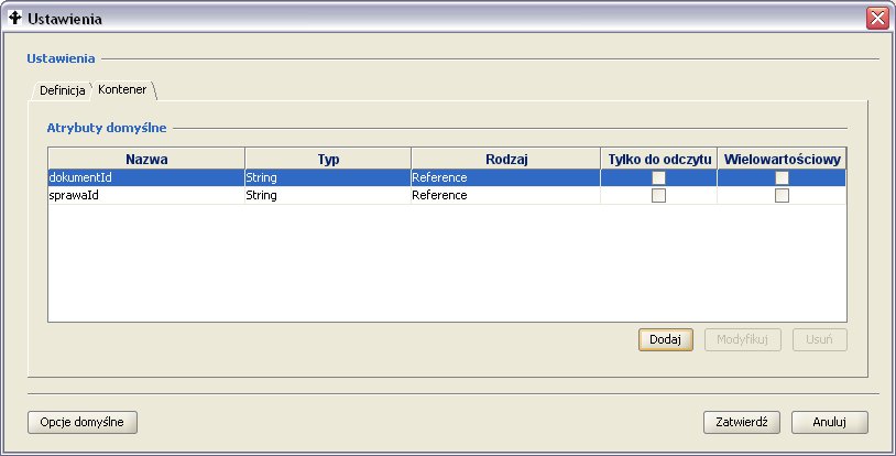
Figure 6. Defining default process attributes.
You can return to the standard configuration settings at any time. To do this, click the Default Options button.
Configuration parameters can be exported and then imported. This is useful when we work on two different servers and want to transfer the configuration in order to increase the ergonomics of defining processes. Saving in the database also makes the configuration the default configuration for all users of the process design tool. The locally saved configuration always overrides the global configuration , unless the user forces it by selecting the default options .
Automatic editing of changes in the Process
To increase the ergonomics of the designer tool, an additional mechanism for keeping up with changes in the naming of global variables (container attributes) has been implemented. If we change the name of an existing container attribute, the system will automatically update its name in all calls and assignments of this attribute
Process Instance Execution Model
The class diagram of the runtime process model , which is shown in Figure 7 , is created based on the corresponding process definition available in the process repository of a given docuRob® WorkFlow installation . The meaning of the individual attributes of the model classes is presented in Table 2 .
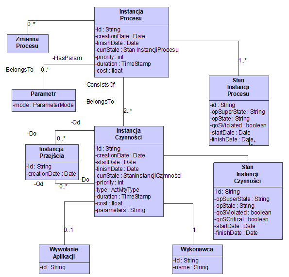
Figure 7. Process execution metamodel
| Attribute name | Attribute description |
|---|---|
| id | docuRo ® WorkFlow system level identifier . |
| creationDate | Date the process instance was created. |
| finishDate | Process instance end date. |
| currState | Current state of the process instance. |
| priority | Priority. |
| Quality parameters | |
| duration | Maximum duration of execution of a process instance. |
| cost | Current cost of execution. |
Table 2. Process Instance Attributes
The state model of a process instance is presented in Figure 8 . A process instance reflects its state in two planes: through operational states and through states related to the quality of service (QoS). Operational states indicate what is happening with a given process instance. QoS states reflect how quality constraints are met.
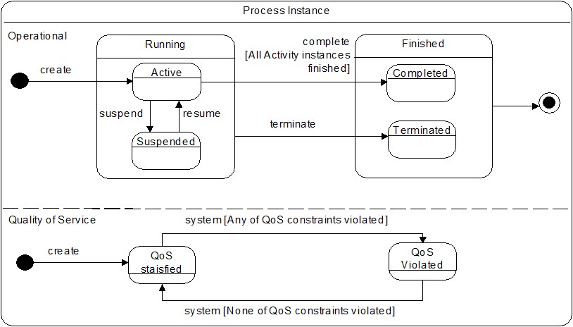
Figure 8. Process instance state model
The characteristics of individual states of the process instance are described in Table 3 .
| State Name | State Description |
|---|---|
| Operational states | |
| Running | Above state indicating that a process instance is executing. |
| Running.Active | The process execution has started. |
| Running.Suspended | The process instance has been paused. |
| Finished | Above the state indicating that the process has completed. |
| Finished.Completed | Positive termination of a process instance. |
| Finished.Terminated | Interrupting execution of a process instance.. |
| QoS states | |
| QoS satisfied | All time constraints met, |
| QoS violated | At least one time constraint not met. |
Table 3. Process Instance States
The meaning of the attributes of the activity instances is presented in Table 4 , and the characteristics of the individual states of the process activity instances are presented in Table 5.
| Attribute name | Attribute description |
|---|---|
| id | docuRob ® WorkFlow system level identifier . |
| creationDate | Instance creation date. |
| startDate | Instance start date. |
| finishDate | Date of completion of activity. |
| currState | Current status. |
| priority | Priority |
| type | Action type (atomic, compound, control). |
| duration | Current execution time of the activity instance. |
| deadline | Time limit for completing the activity. |
Table 4. Activity instance attributes
The model of activity instance states ( Figure 9 ) is also presented using a state diagram. This model distinguishes two types of states: those related to the operability of the activity instance and those related to the quality of the service being performed.
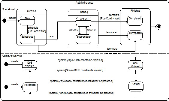
Figure 9. Activity instance state model
An activity instance represents the execution of an activity by a given performer. If an activity is performed by more than one performer, a separate activity instance is created for each of them. An activity instance is called a Task according to the BPMN 2.02 standard specification .
| State Name | State Description |
|---|---|
| Operational states | |
| Running | A super-state indicating that an activity instance is executing. |
| Created | Create a task. |
| Created.New | Task created after pre action execution. |
| Created.Scheduled | Task assigned to a specific performer, |
| Running.Active | The execution of the activity has begun. |
| Running.Suspended | The activity instance has been paused. |
| Finished | Above the state indicating that the activity has completed. |
| Finished.Completed | Positive completion of an activity instance. |
| Finished.Terminated | Interrupting the execution of an activity instance. |
| QoS states | |
| QoS satisfied | All time constraints met, |
| QoS violated | At least one time constraint not met. |
Table 5. Activity instance states